headerphoto
Showing posts with label electronic. Show all posts

How to turn on the led of arduino, which is call the led pin?


At the picture above, the led pin is marked as L and to turn it on is very easy, just

upload the sketch

bellow. If you success to upload the code (sketch), the led pin will turn on for 1 second, then turn off for 1 second, and roll it over again and again.


/****************************************/
/* ARDUINO SKETCH (1): BLINK, FLIP-FLOP */
/* TURN ON THE LED AT PIN 13 */
/****************************************/

#define led 13

void setup(){
pinMode(led, OUTPUT);
}

void loop(){
digitalWrite(led, HIGH);
delay(1000);
digitalWrite(led, LOW);
delay(1000);
}


Read more »»

As someone who studied electricity, you will be confused with the imaginary calculations such as: (30 + j25) × (40 ∟ 65°). Two models number in parentheses is a complex numbers, where 30 + j25 is call rectangular form and 40 ∟ 65° is call polar form.

Rectangular form is a number that can be put in the form x + jy, where x and y are real numbers and j is called the imaginary unit. In this expression, x is called the real part and y the imaginary part of the complex number.

Polar form is a number that can be put in the form r ∟ φ°, where r is absolute value and φ is angle value. Together, r and φ give another way of representing complex numbers.

To solve the above calculations problem, you should have a scientific calculator, and you should know how to operate it. Can you do it? And to make it easier I will give complex numbers conversion software, free for you.

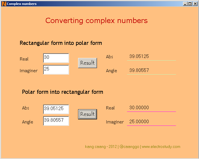
Download at Google code here ★ Converting complex numbers ★. Download and save rar file (size 10.4 kB), extract and run, as shown below


Read more »»

Magnetic relay or just called relay is a type of switch that is controlled by an electric current. The main part of relay consists of a coil and contacts. Relay coil wrapped around the core. There is an iron armature will be attracted to the core when a current flows through the coil. Armature is mounted on a spring-loaded lever. When the armature attracted to the core, relay contact will change its position from normally closed contacts to the normally open contacts.

A relay can be activated in about 10 ms. Most relay placed in packaging that fully closed, as shown below.

relay

Most among the relay has contacts type of SPDT switch, but there are also several types of DPDT switch, TPDT switch (Triple Pole Double Throw) and QPDT switch (Quadruple Pole Double Throw, as shown above right).

The important thing to note on a relay that will be used is the coil voltage and the maximum, current and voltage contacts.

Larger relays can be connected to the currents up to 10 A at a voltage of 250 VAC. The DC maximum voltage for switching is always lower than AC maximum voltage, sometimes even just half of the AC maximum voltage.

Symbol relay with QPDT contact switch

Symbol relay

Read more »»

micro switchMicro term on the micro switch, doesn't mean that the size of micro switch is small. This name indicates that the keys used to operate micro switch, only shifted by a very small distance.

Micro switch is type of very sensitive switch, just a little pressure on a lever may cause the switch move from one position to another. Most micro switches have contacts SPDT type, so that the switch can be used to connect or disconnect, or both simultaneously.

SPDT contacts in the micro switch is generally composed of three terminal tag, such a Common line, NO (Normally Open) contact and NC (Normally Closed) contact. Contacts are equipped with spring-loaded, on normal condition, Common line will be connected to NC contact.

There are various types of micro switch, which can be used according to the applications where the switch should be operated mechanically. Image below shows the various types of micro switches.

macam-macam-microswitch.jpg

For example, a micro switch can be mounted in such a way in a refrigerator. Common line and NC contact connected to a lamp. When the door closed, contacts will open and the light will turn off. When the doors opened, the contacts will close and light will turn on.

Read more »»

Circuit power supply 12 VDC 5 A usually used for audio amplifier. With the characteristics of its pure DC output voltage, big power, and very stable, to avoid hum or noise on the speakers.

power supply amplifierPower supply audio amplifier
Schematics power supply 12 VDC 5 A as shown below

big_power_supply_5A
Components are required:
  1. C1 = Elco 6800 uF/25 V
  2. C2 = Elco 100 uF/16 V
  3. C3 = Elco 2200 uF/25 V
  4. D1, D2 = Diodes IN 5402
  5. Q1 = Transistor 2N 3055
  6. IC1 = Regulator 7812
  7. T1 = Transformer step down 220 V/15 V 5 A CT

Read more »»

Table data of high power transistors below, provide information about the type of (BD131, BD132, BD139, BD140, BD437, BD438, BD679, BD680, 2N3055, MJ2955, TIP31, TIP32, TIP33, TIP34, TIP35, TIP36, TIP41, TIP42, TIP2955, and TIP3055), type (PNP or NPN), supply voltage, current, and maximum power, HFE, HFE bias, the opponent (if the PNP type replaced with NPN type, or reverse), and packaged transistor (click here to view the package).


High power transistors or large signal transistors used for general purpose, amplifier circuit, the output power circuit, or a large current circuit switch.

Read more »»

Table data of low power transistors below, provide information about the type of (BC107, BC108, BC109, BC140, BC141, BC160, BC161, BC177, BC178, BC179, BC327, BC328, BC337, BC338, BC546, BC547, BC548, BC556, BC557, BC558, BC639, and BC640), type (PNP or NPN), supply voltage, current, and maximum power, HFE, HFE bias, the opponent (if the PNP type replaced with NPN type, or reverse), and packaged transistor (click here to view the package).

low-power-transistors-data-table
Low power transistors or small signal transistors used for general purpose, small-signal amplifier, or the circuit switch.

Read more »»

Packaged transistors are varied, low power transistor package will be different with the packaging of high power transistor. Low-power transistors made with the packaging from plastic or metal. Low power transistor packaging made of plastic material having a characteristic surface is flat, while those made of metal having a protrusion (tag) on the plate underneath.

Transistors with a higher power, usually made of plastic packaging, metal, or a mixture of plastic and metal. Metals in the body transistor, generally signifies a collector terminal, and specialized in high power transistor, the metal tag is useful for attaching a heat sink or appliance exhaust heat dissipation that occurs during the process.

Packaging features are intended to identify the terminal legs of the transistor. Most of the packaged transistor is grouped with the term TO (Transistor Outline).

Picture below is a transistor package which we use in the electronics world, including TO-92a, TO-92B, TO92C, TO-126, TO-220, TO-18, TO-39, TO-3, and TO-3P (N), following the legs or the terminal base, emitter, and collector.

transistors-package

Read more »»

Key switch
Key switch is a type of switch that can only be turned on and turned off by using a key. Only a key partner and the right locking device which can be used to operate the switch. Key switch can be used in applications that require high levels of security, such as electrical control circuit in the industry.

Examples of key switch as shown in the picture below

Key switch
DPDT switch
Toggle switch, rocker switch, and slide switch, can also be made ​​in a Double Pole Double Throw version, which is abbreviated with DPDT switch. Form of this switch combine two separate switches in one unit, but they operated together.

DPDT switch can be used to connect two circuits at the same time. These switches can also be connected to the neutral wire line and the line wire voltage of the source at once. When a switch is in off state, the electrical equipment connected to the switch is totally isolated from the source voltage.

Symbol of DPDT switch as shown in the picture below

Symbol of DPDT switch

Read more »»

Rocker switch
Rocker switch works the same way as a toggle switch, where there is a lever that can be pressed up and down. Lever of the rocker switches are usually called to rocker lever, shaped like an electric bell button.

Generally there are two numbers on the rocker lever, numbers 1 and 0. When the lever is pressed on number 1, indicating that the switch in the On position, and when the lever is pressed on number 0, indicating a switch in the Off position.

Examples of rocker switch as shown below

Rocker switch
Slide switch
Slide switches are used for similar purposes to the use of toggle switches, but the slide switch is operated by using a sliding knob.

Examples of slide switches as shown in the picture below

Slide switch

Read more »»

Rotary switchRotary switch is a switch type which is operated by way of played. These switches are used to connect one line to one other line, among several lines that already exist. Often, several pieces of rotary switch is used in the same unit.

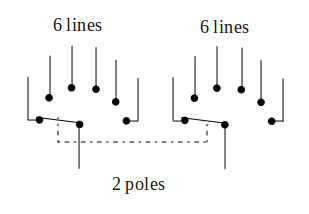
Examples of common use rotary switch is serves to select a range of measurements on an AVO meter or a multimeter, or to choose a power supply voltage. This type of switch has one or more contacts are surrounded by a ring with 12 stationary contacts. Such switches are made with the composition different contacts. These arrangements can be either 1 pole of 12 lines, 2 poles 6 lines, 3 poles 4 lines or 4 poles 3 lines.

The symbol of rotary switch with 2 poles 6 lines shown bellow

rotary-switc-2-poles-6-lines

Read more »»

Press switchPress switch is a type of switch that is operated by pressing a button. There are two types of press switch, ie push to make (PTM) switch and push to break (PTB) switch.

Most of the press switch is a kind of the PTM switch. By pressing a button PTM switch, the contacts will be depressed until the switch is closed and touch each other. While by pressing a button switch type of PTB switch, the contacts are normally closed contact, but will be forced open when the button is pressed.

Each type of PTM switch and PTB switch, can work to connect or disconnect during a moment or locking (latching). A switch work during a moment, will close (connect) or open (disconnect) as long as the button is pressed. When the button is released the switch will return to its original position.

Connection on the switch that locks, the button will remain in a depressed position after the first time pressed. Switch contacts will remain closed or open, depending on the type of switch is concerned. You must press the button again to unlock and return the buttons to its normal position.

Press switches are widely used in various industrial applications, the motor control circuit, and can also be used to connect power to the lights, radio devices, and other electrical equipment.

Symbol press switch such us PTM switch and PTB switch as shown below

Symbol press switch such us PTM switch and PTB switch

Read more »»

Toggle switchToggle switch is the simplest form of switch, operated by a toggle lever that can be pressed up and down. According to the convention, position of the lever downwards to indicate OFF conditions or switch contacts is disconnected, and position of the lever upwards to indicate ON conditions or switch contacts are connected.

Toggle switch have two terminal tag, which indicates that switch have a contact type single pole single throw or single pole single direction, which is usually referred to as SPST switch.

Toggle switch that are smaller have three terminals tag, which indicates that switch have a contact type single pole double throw or single pole two direction, normally abbreviated with the SPDT switch. Terminal tag at the center is the line common current flow and can establish contact with either of these two other tag. Such contacts are called changeover contacts switch.

Symbol for SPST switch and SPDT switch as shown below

Symbol for SPST and SPDT switches

Read more »»

The switch is a device used to control the flow of electrical current into the circuit. In the previous discussion about electric current, the electrical current will only flow in a closed circuit. So as to create a current to flow or not, we can use the switch.

Current flows when the switch contacts touch each other. In this state, the switch is said to be closed or made ​​contact.

Current can not flow into the circuit when the contacts are not touching. In this state the switch is said to be opened or lost contact.

Other terms of the condition of the switch is On and Off. On condition occurs when the contacts is made​​, and the Off condition occurs when the contact is lost.

symbols-of-switch
There are various types of switches are used for many different purposes. Figure above shows the general symbols of switch, Off the conditions shown in Figure A, and On conditions are shown in Figure B.

Read more »»

Electronic components are divided into two types, namely passive components and active components. Passive component is a component that can not lead to increase in the electric power circuit, examples of passive components are resistors, capacitors, and inductors.

While the active component is a component that can lead to increase in the electric power circuit, examples of active component is tansistor.

Resistor has the ability to convert electrical energy into heat. Inductor has the ability to convert electrical energy into magnetic force. However, neither of the two components that can lead to the addition of power in the circuit, it is called passive components.

Instead of a transistor receives the low power input (small current) and converts it into a high power output (large current), the transistor is called the active component.

Read more »»

Gain transistor or the acquisition of the current generated by the transistor, commonly referred to as the small signal current gain, while the magnitude of the gain is written with symbols HFE. This gain value is determined when the transistor is made, and with a very diverse range. For example, type BC548 NPN transistor has a range between 110 and 800.

Under conditions of saturation, the gain is the ratio of collector current to base current, or by the equation

HFE = IC / IB

Example question:
Calculate the gain transistor in the circuit below

Calculate the gain transistor
completion:
Known value of IC = 60 mA, IB currents obtained by Ohm's law
IB = VBB - VBE / RB
IB = (6 - 0.7) V / 10 kΩ
IB = 5.3 V / 10 kΩ
IB = 0.00053 A
IB = 0.53 mA
The amount of gain or HFE = IC / IB = 60 mA / 0.53 mA = 113

Read more »»

In the switch circuit, transistor sometimes be in the inactive state, where there is no any current flows through it. These conditions is called transistor's cut off condition.

Figure A shows the state of the transistor in a cut off condition

transistor_cut_off
At other times when the transistor is in the fully active state, where there are only a relatively small potential difference between the emitter and collector terminals. These conditions is called transistor's saturated condition.

Figure B shows the state of the transistor in saturated condition.

transistor_saturation

Read more »»

symbol_of_thyristorThe Thyristors is a semiconductor switch either of the pnpn or npnp type, whose bi-stable action depends on regenerative internal feedback. Figure at the left is symbol of thyristor, where A is anoda terminal, C is cathode terminal and G is gate terminal.

The four layer device is usually silicon although germanium has been used. Devices with the two endmost layers only connected to external terminals (anode and cathode) are called four layer diode, those with three layers accessible (anode, cathode, and p gate) are called thyristors. SCR (Silicon Controlled Rectifier) is other name of thyristors.

The structure is best visualized as consisting of two transistors, a pnp and an npn interconnected to form a regenerative feedback pair as shown in figure bellow.

thyristor_configuration
Current gain around the internal feedback loop G (Gate) is hfe1 x hfe2, where hfe1 and hfe2 are the common emitter current gains of the individual sections. If Ico1 is the collector to base leakage current of the npn section and Ico2 is the collector to base leakage of the pnp section, then:
for the pnp section: Ic1 = hfe1 (Ic2 + Ico1) + Ico1
for the npn section: Ic2 = hfe2 (Ic1 + Ico2) + Ico2
and the total anode to cathode current Ia = (Ic1 + Ic2)

from which Ia = [(1 + hfe1) (1 + hfe2) (Ico1 + Ico2)] / [1 – (hfe1) (hfe2)]

With a proper bias applied, ie positive anode to cathode voltage, the structure is said to be in the forward blocking or high impedance 'off ' state. The switch to the low impedance 'on' state is initiated simply by raising the loop gain G to unity. As this occurs the circuit starts to regenerate, each transistor driving its mate to saturation. Once in saturation all junctions assume a forward bias, and the total potential drop across the device approximates to that of a single junction. Anode current is then only limited by the external circuit.

To turn off thyristor in a minimum time it is necessary to apply a reverse voltage and under this condition the holes and electrons in the vicinity of the two end junctions will diffuse in these junction and result in a reverse current in the external circuit. The voltage across the thyristor will remain at about 0.7 V positive as long as an appreciable reverse current flows.

After the been removed, the reverse current will cease and the junction assume a blocking state. The turn-off time is usually of the order of 10-15 μs. The fundamental difference between the transistor and thyristor is that with the former conduction can be stopped at any point in the cycle because the current gain is less than unity. This is not so far the thyristor, conduction only stopping at a current zero.

Read more »»

There's a lot of photo electric devices, such as photo-cell relays, photoelectric switch units, silicon photo-electric cells and silicon blue cell.

Photo-cell relays. Basic component of photo-cell relay is an integral light activated switch. It combines a silicon planar photo diode with integrated circuit on a single substrate to provide a highly sensitive photo electric device. Operation is such that when light of a selected intensity falls upon it, the device switches on and supplies current to an external load. When the light intensity falls below the critical level the load current is turned off. This critical level can be adjusted within wide limits.

The equipment comprises a projector containing a light emitting diode and optical system projecting a beam of light either directly or by reflection onto a photo-cell mounted in a receiver unit. The relay coil is energized when the light beam is made and de-energized when it is broken. Thus the relay contacts can provide a change over operation which can be used to perform some external control function. The control unit can contain additional circuitry such as time delays or LED failure circuits to meet a wide variety of application requirement. System are available for operating over distances from 10-15 mm up to 50 m or more.

Applications include conveyor control, paper breakage alarm, carton sorting and counting, automatic spraying, machinery guarding, door opening, level controls, burglar alarms, edge alignment control and punched card reading.

Photoelectric switch units. Light sensitive switches are used for the economical control of lighting. They consist of a photo-cell which monitors the intensity of the light and automatically switches the lighting on or off. Construction of s typical unit is shown in figure 4.10 and this will switch a resistive load of 3 A at 250 VAC. The unit is based on a cadmium-sulphide cell and it incorporates a 2 minute time delay to prevent 'hunting'. Larger units are available with resistive switching capacities up to 10 A.

Silicon photo-electric cells. These cells are designed to provide large output current even under low illumination intensities. Currents of several milliamperes are obtainable. Structure of a photo-electric cell will be seen to consist of a thin p type layer on n type silicon. Due to its linear photo-voltaic effect there is no need for a bias power source. A linear output can be obtained by selecting a suitable load resistance for a wide range of illuminance. Like the silicon blue cell, described below, it has no directivity of receiving light, so there is no need to adjust the optical axis as is the case with photo-transistors.

Silicon blue cell. The sharps silicon blue cell manufactured by photain controls is claimed to be the world's first photo-electric diode possessing high sensitivity over the entire visible light spectrum. It is more reliable than the selenium or cadmium-sulphide photo-cells and has superior time response. No bias power is required, it has a lower noise level than the other two type and it is non-directional.

Application include illumination meters, exposure meters, optical readouts of film sound tracks, colorimetry, flame spectrometry, photo spectrometry and color or pattern recognition equipment.

Read more »»

We can create a power supply for electronic equipment with voltage range from 3 V, 4.5 V, 6 V, 7.5 V, 9 V, to 12 V.

Add component such a rocker switch or a slide switch as the main switch, and put one LED as an indicator tool.

Power supply circuit with variable voltage as shown below

Click to enlarge

Components are required:
  1. S1 = Rocker switch
  2. S2 = Rotary switch (2 pole 6 lanes)
  3. T1 = Step-down transformer without ct (220V/12V 500mA)
  4. D1, D2, D3, D4 = Diodes IN4002
  5. D5 = LED
  6. R1 = Resistor 220 Ω
  7. C1 = Elco (electrolytic capacitor) 2200 μF/16V

Read more »»

Previous