headerphoto
Showing posts with label component. Show all posts

Magnetic relay or just called relay is a type of switch that is controlled by an electric current. The main part of relay consists of a coil and contacts. Relay coil wrapped around the core. There is an iron armature will be attracted to the core when a current flows through the coil. Armature is mounted on a spring-loaded lever. When the armature attracted to the core, relay contact will change its position from normally closed contacts to the normally open contacts.

A relay can be activated in about 10 ms. Most relay placed in packaging that fully closed, as shown below.

relay

Most among the relay has contacts type of SPDT switch, but there are also several types of DPDT switch, TPDT switch (Triple Pole Double Throw) and QPDT switch (Quadruple Pole Double Throw, as shown above right).

The important thing to note on a relay that will be used is the coil voltage and the maximum, current and voltage contacts.

Larger relays can be connected to the currents up to 10 A at a voltage of 250 VAC. The DC maximum voltage for switching is always lower than AC maximum voltage, sometimes even just half of the AC maximum voltage.

Symbol relay with QPDT contact switch

Symbol relay

Read more »»

micro switchMicro term on the micro switch, doesn't mean that the size of micro switch is small. This name indicates that the keys used to operate micro switch, only shifted by a very small distance.

Micro switch is type of very sensitive switch, just a little pressure on a lever may cause the switch move from one position to another. Most micro switches have contacts SPDT type, so that the switch can be used to connect or disconnect, or both simultaneously.

SPDT contacts in the micro switch is generally composed of three terminal tag, such a Common line, NO (Normally Open) contact and NC (Normally Closed) contact. Contacts are equipped with spring-loaded, on normal condition, Common line will be connected to NC contact.

There are various types of micro switch, which can be used according to the applications where the switch should be operated mechanically. Image below shows the various types of micro switches.

macam-macam-microswitch.jpg

For example, a micro switch can be mounted in such a way in a refrigerator. Common line and NC contact connected to a lamp. When the door closed, contacts will open and the light will turn off. When the doors opened, the contacts will close and light will turn on.

Read more »»

Packaged transistors are varied, low power transistor package will be different with the packaging of high power transistor. Low-power transistors made with the packaging from plastic or metal. Low power transistor packaging made of plastic material having a characteristic surface is flat, while those made of metal having a protrusion (tag) on the plate underneath.

Transistors with a higher power, usually made of plastic packaging, metal, or a mixture of plastic and metal. Metals in the body transistor, generally signifies a collector terminal, and specialized in high power transistor, the metal tag is useful for attaching a heat sink or appliance exhaust heat dissipation that occurs during the process.

Packaging features are intended to identify the terminal legs of the transistor. Most of the packaged transistor is grouped with the term TO (Transistor Outline).

Picture below is a transistor package which we use in the electronics world, including TO-92a, TO-92B, TO92C, TO-126, TO-220, TO-18, TO-39, TO-3, and TO-3P (N), following the legs or the terminal base, emitter, and collector.

transistors-package

Read more »»

Key switch
Key switch is a type of switch that can only be turned on and turned off by using a key. Only a key partner and the right locking device which can be used to operate the switch. Key switch can be used in applications that require high levels of security, such as electrical control circuit in the industry.

Examples of key switch as shown in the picture below

Key switch
DPDT switch
Toggle switch, rocker switch, and slide switch, can also be made ​​in a Double Pole Double Throw version, which is abbreviated with DPDT switch. Form of this switch combine two separate switches in one unit, but they operated together.

DPDT switch can be used to connect two circuits at the same time. These switches can also be connected to the neutral wire line and the line wire voltage of the source at once. When a switch is in off state, the electrical equipment connected to the switch is totally isolated from the source voltage.

Symbol of DPDT switch as shown in the picture below

Symbol of DPDT switch

Read more »»

Rocker switch
Rocker switch works the same way as a toggle switch, where there is a lever that can be pressed up and down. Lever of the rocker switches are usually called to rocker lever, shaped like an electric bell button.

Generally there are two numbers on the rocker lever, numbers 1 and 0. When the lever is pressed on number 1, indicating that the switch in the On position, and when the lever is pressed on number 0, indicating a switch in the Off position.

Examples of rocker switch as shown below

Rocker switch
Slide switch
Slide switches are used for similar purposes to the use of toggle switches, but the slide switch is operated by using a sliding knob.

Examples of slide switches as shown in the picture below

Slide switch

Read more »»

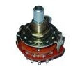
Rotary switchRotary switch is a switch type which is operated by way of played. These switches are used to connect one line to one other line, among several lines that already exist. Often, several pieces of rotary switch is used in the same unit.
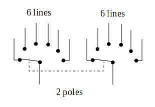
Examples of common use rotary switch is serves to select a range of measurements on an AVO meter or a multimeter, or to choose a power supply voltage. This type of switch has one or more contacts are surrounded by a ring with 12 stationary contacts. Such switches are made with the composition different contacts. These arrangements can be either 1 pole of 12 lines, 2 poles 6 lines, 3 poles 4 lines or 4 poles 3 lines.

The symbol of rotary switch with 2 poles 6 lines shown bellow

rotary-switc-2-poles-6-lines

Read more »»

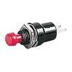
Press switchPress switch is a type of switch that is operated by pressing a button. There are two types of press switch, ie push to make (PTM) switch and push to break (PTB) switch.

Most of the press switch is a kind of the PTM switch. By pressing a button PTM switch, the contacts will be depressed until the switch is closed and touch each other. While by pressing a button switch type of PTB switch, the contacts are normally closed contact, but will be forced open when the button is pressed.

Each type of PTM switch and PTB switch, can work to connect or disconnect during a moment or locking (latching). A switch work during a moment, will close (connect) or open (disconnect) as long as the button is pressed. When the button is released the switch will return to its original position.

Connection on the switch that locks, the button will remain in a depressed position after the first time pressed. Switch contacts will remain closed or open, depending on the type of switch is concerned. You must press the button again to unlock and return the buttons to its normal position.

Press switches are widely used in various industrial applications, the motor control circuit, and can also be used to connect power to the lights, radio devices, and other electrical equipment.

Symbol press switch such us PTM switch and PTB switch as shown below

Symbol press switch such us PTM switch and PTB switch

Read more »»

Toggle switchToggle switch is the simplest form of switch, operated by a toggle lever that can be pressed up and down. According to the convention, position of the lever downwards to indicate OFF conditions or switch contacts is disconnected, and position of the lever upwards to indicate ON conditions or switch contacts are connected.

Toggle switch have two terminal tag, which indicates that switch have a contact type single pole single throw or single pole single direction, which is usually referred to as SPST switch.

Toggle switch that are smaller have three terminals tag, which indicates that switch have a contact type single pole double throw or single pole two direction, normally abbreviated with the SPDT switch. Terminal tag at the center is the line common current flow and can establish contact with either of these two other tag. Such contacts are called changeover contacts switch.

Symbol for SPST switch and SPDT switch as shown below

Symbol for SPST and SPDT switches

Read more »»

Electronic components are divided into two types, namely passive components and active components. Passive component is a component that can not lead to increase in the electric power circuit, examples of passive components are resistors, capacitors, and inductors.

While the active component is a component that can lead to increase in the electric power circuit, examples of active component is tansistor.

Resistor has the ability to convert electrical energy into heat. Inductor has the ability to convert electrical energy into magnetic force. However, neither of the two components that can lead to the addition of power in the circuit, it is called passive components.

Instead of a transistor receives the low power input (small current) and converts it into a high power output (large current), the transistor is called the active component.

Read more »»

symbol_of_thyristorThe Thyristors is a semiconductor switch either of the pnpn or npnp type, whose bi-stable action depends on regenerative internal feedback. Figure at the left is symbol of thyristor, where A is anoda terminal, C is cathode terminal and G is gate terminal.

The four layer device is usually silicon although germanium has been used. Devices with the two endmost layers only connected to external terminals (anode and cathode) are called four layer diode, those with three layers accessible (anode, cathode, and p gate) are called thyristors. SCR (Silicon Controlled Rectifier) is other name of thyristors.

The structure is best visualized as consisting of two transistors, a pnp and an npn interconnected to form a regenerative feedback pair as shown in figure bellow.

thyristor_configuration
Current gain around the internal feedback loop G (Gate) is hfe1 x hfe2, where hfe1 and hfe2 are the common emitter current gains of the individual sections. If Ico1 is the collector to base leakage current of the npn section and Ico2 is the collector to base leakage of the pnp section, then:
for the pnp section: Ic1 = hfe1 (Ic2 + Ico1) + Ico1
for the npn section: Ic2 = hfe2 (Ic1 + Ico2) + Ico2
and the total anode to cathode current Ia = (Ic1 + Ic2)

from which Ia = [(1 + hfe1) (1 + hfe2) (Ico1 + Ico2)] / [1 – (hfe1) (hfe2)]

With a proper bias applied, ie positive anode to cathode voltage, the structure is said to be in the forward blocking or high impedance 'off ' state. The switch to the low impedance 'on' state is initiated simply by raising the loop gain G to unity. As this occurs the circuit starts to regenerate, each transistor driving its mate to saturation. Once in saturation all junctions assume a forward bias, and the total potential drop across the device approximates to that of a single junction. Anode current is then only limited by the external circuit.

To turn off thyristor in a minimum time it is necessary to apply a reverse voltage and under this condition the holes and electrons in the vicinity of the two end junctions will diffuse in these junction and result in a reverse current in the external circuit. The voltage across the thyristor will remain at about 0.7 V positive as long as an appreciable reverse current flows.

After the been removed, the reverse current will cease and the junction assume a blocking state. The turn-off time is usually of the order of 10-15 μs. The fundamental difference between the transistor and thyristor is that with the former conduction can be stopped at any point in the cycle because the current gain is less than unity. This is not so far the thyristor, conduction only stopping at a current zero.

Read more »»

transistorTransistor is an electronic component semiconductor, has ability to control the effective resistance by controlling the main signal (voltage and amperage) from a distance.
There are two types of transistors, namely a bipolar junction transistor or abbreviated by BJT, such as PNP and NPN, and unipolar transistor junction transistor or abbreviated by UJT, such as FET and MOSFET.

Transistors made from crystalline silicon or germanium, where a layer of N type silicon layer sandwiched by two types of P. Conversely it could also be made transistor consisting of two N-type silicon layers sandwiching a layer of type P. Both transistors are kind of BJT transistor, or PNP and NPN type.

In general, BJT transistor has three terminals, ie base (abbreviated with the letter B), collector (abbreviated with the letter C), and emitter (abbreviated with the letter E).

Below is a symbol of PNP and NPN transistor

symbol_NPN_PNP_transistor

Read more »»

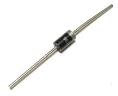
diodeDiode is packaged in a small capsule made ​​of glass or plastic. Diode packaging has two wire terminals, one is called anode, while the other is called cathode. Usually there is a ring worn on the body diode indicating which terminal is the cathode.

A diode is generally made of silicone. Silicon is material that is not a conductor, but is not also as an insulator. Silicon is a semiconductor material. This means the characteristics of silicon is different from usual conductor materials, such as copper or iron.

A small amount of a substance mixed into the silicon to give special characteristics to the material of this diode.

Major constituent of the diode is the connection P - N or called with P - N Junction.

pn-junction
Below is symbol of diode

symbol of diode
Forward Biased and Reverse Biased Diode

forward-reverse-biased-diode
When the diode is connected as in Figure A above, where the anode wire is connected to the positive pole and the cathode connected to the negative pole of battery, we say that forward biased diode. A diode will only conduct electricity (turn on a light) when given forward bias.

When a diode is connected with reversed polarity as shown in Figure B, where the cathode wire is connected to the positive pole and the anode connected to the negative pole of battery, we say that reverse biased diode . A diode will not conduct electricity (turn off a light) when given reverse bias.

Read more »»

A light dependent resistor or LDR, composed of a disk of semiconductor material with two electrodes on its surface. In its function, the LDR is a type of resistor whose value is affected by light.

LDR
In an environment of dark or under dim light, the disc material contain free electrons in a relatively very small amount. There are few free electrons to flow of electric charge. This means that, the material is a poor conductor for electrical current. In other words, the value of very high resistance materials.

In an environment with enough light, more electrons can escape from the atoms of this semiconductor material. There are more free electrons that can drain the electric charge. Under these circumstances, the material is of a good conductor. Low electrical resistance material. The more bright light on the material, the more electrons are available, and the lower the electrical resistance of this material.

Below is a symbol of LDR

symbol of LDR
Conclusion:
  • LDR is a type of resistor whose value is affected by light
  • In the dark, the LDR resistance is very high
  • In the light of circumstances, the LDR resistance is very low

Read more »»

Thermistor (thermal resistor) is made of semiconductor materials. This component can be made in the form of discs, bars, or grains. Thermistor grain has a diameter only a few millimeters. In some thermistor grain, grain semiconductor glass wrapped by a capsule.

NTC thermistor
Because of very small size, thermistor grain can react very quickly to temperature changes. Thermistor terminals has two legs.

Most of the thermistor has resistance whose value will become smaller with increasing temperature. Thermistor type is called a negative temperature coefficient thermistor or NTC thermistor.

There is also a thermistor having a resistance value will be further enlarged with increasing temperature. Thermistor type is called a positive temperature coefficient thermistor or PTC thermistor.

Thermistor is used in the circuits or temperature gauges that provide specific responses to temperature changes. This component can also be used in circuits that will have the disorder, or even damage, caused by temperature changes.

Below is a symbol of thermistor

symbol of thermistor
Conclusion:
  • Thermistor is a type of resistor whose value is affected by temperature
  • There are two types of thermistor, which is NTC and PTC
  • NTC Thermistor gets a smaller resistance value with increasing temperature
  • PTC Thermistor gets a greater resistance value with increasing temperature

Read more »»

Light emitting diode or better known as LEDs (LED), are electronic components that can produce light when an electric current flowing through it.

LED is described with the following symbol

 LED symbol
At the beginning LED is only made in red, but now the colors of yellow, green, blue, and orange are also available on the market. There is also an infrared LED, which produces infrared light.

the colors of led
LED generally has a dome-shaped packaging material made ​​of plastic, with a protruding edge or rim at the bottom of the dome. There are two wire terminals on the bottom, which is cathode and anode. Usually the cathode wire is shorter than the anode wire, see the picture below

anode cathode led
LED requires about 20 mA current to emit light with maximum brightness, although as small as 5 mA current can still produce visible light. An average voltage drop the LED is 1.5 V, thus the supply voltage is 2 V can turn most of LED with maximum brightness. With levels higher voltages, LEDs can be damaged and caught fire when a given forward voltage exceeds 2 V.

Read more »»

An AVO meter (Ampere, Volt, Ohm meter) or a multimeter can measure several different electrical quantities, usually a current, voltage, and resistance. There are two kinds of multimeter, namely analog and digital.

multitester
Both multimeter has a socket or a hole for the probe step on the test rod. Positive hole is marked with a + symbol is usually red, common hole (negative) is marked with a COM or symbol - usually black. Some multi meters have a positive second socket, which should be used to measure high voltages.

probe-multitester
Both types of meter has a rotary knob to select where the quantity to be measured. This rotary knob is often also used to select a range of measurements. On an analog meter, you must connect the negative probe to the common measurement points more negative and the red probe to the measuring point is more positive. When you connect it backwards, the needle will swing downward zero. Remove immediately the two probes because it will cause damage to the meter.

Digital meters often have features otopolaritas. With this feature, the meter will show a minus sign on the left digit readout, when both probes are connected to the measurement points in reverse.

With an analog meter, there is a reading error problem when you do not read the measurement scales in a straight line from the top. Such errors are called parallax error. To help you avoid this, the meter is equipped with a curved mirror on the scale readings. You can see the reflection or shadow of the needle gauge on this mirror. When doing readings, move your head left and to right until you get the shadow coincides with a needle gauge needle. This ensures that you are looking straight down the scale and the reading will be correct.

jarum-multitester-analog
Digital meters may also have features auto ranging. This feature allows the meter to choose the appropriate range automatically when the measurement was made.

Read more »»

Previous