headerphoto
Showing posts with label circuit. Show all posts

Circuit power supply 12 VDC 5 A usually used for audio amplifier. With the characteristics of its pure DC output voltage, big power, and very stable, to avoid hum or noise on the speakers.

power supply amplifierPower supply audio amplifier
Schematics power supply 12 VDC 5 A as shown below

big_power_supply_5A
Components are required:
  1. C1 = Elco 6800 uF/25 V
  2. C2 = Elco 100 uF/16 V
  3. C3 = Elco 2200 uF/25 V
  4. D1, D2 = Diodes IN 5402
  5. Q1 = Transistor 2N 3055
  6. IC1 = Regulator 7812
  7. T1 = Transformer step down 220 V/15 V 5 A CT

Read more »»

In the past the overload torque requirement has been met by using a large frame size than necessary to meet full load torque requirements, the torque being proportional to the product of the AC supply voltage and the DC field produced by the excitation current.

With thyristor control of excitation current it is possible to use a smaller frame size for a given horse power rating and arrange to boost the excitation by means of a controller to avoid loss synchronism under torque overload conditions.

The excitation current of a synchronous motor may be controlled by supplying the motor field winding from a static thyristor bridge, using the motor supply current to control the firing angle, figure below. A pulse generator varies the firing angle of the thyristors in proportion to a DC control signal from a diode function generator. Variable elements in the function generator enable a reasonable approximation to be made to any of a wide range of compensating characteristics.

simple_compensated_excitation_circuitSimple compensated excitation circuit
When the motor operates a synchronously, i.e. during starting, a high emf is induced in the field winding, and the resulting voltage appearing across the bridge must be limited to prevent the destruction of the bridge elements. This may be done by using a shunt resistor connected as shown.

Where more exacting requirements have to be met, current feed back can be applied to eliminate effects of non-linearity in the pulse generator and rectifier bridge and it will also improve the response of the system to sudden changes of load. Automatic synchronizing is possible without relays by incorporating a slip frequency sensing circuit to control the gate which supplies the control signal to the pulse generator.

Read more »»

We can create a power supply for electronic equipment with voltage range from 3 V, 4.5 V, 6 V, 7.5 V, 9 V, to 12 V.

Add component such a rocker switch or a slide switch as the main switch, and put one LED as an indicator tool.

Power supply circuit with variable voltage as shown below

Click to enlarge

Components are required:
  1. S1 = Rocker switch
  2. S2 = Rotary switch (2 pole 6 lanes)
  3. T1 = Step-down transformer without ct (220V/12V 500mA)
  4. D1, D2, D3, D4 = Diodes IN4002
  5. D5 = LED
  6. R1 = Resistor 220 Ω
  7. C1 = Elco (electrolytic capacitor) 2200 μF/16V

Read more »»

Diode bridge rectifier's circuit is a full-wave rectifier circuit that uses four diodes, and connected as a bridge. Unlike the full-wave rectifier discussion in previous article, where the circuit uses two diodes, this time is full-wave rectifier circuit with four diodes.

Beside different from amounts of diodes, other difference lies in use of a transformer, which transformer used in the bridge rectifier circuit system is not a transformer which has ct (center tap) or using a conventional transformer without ct.

Diode bridge rectifier's circuit as shown below

Diode bridge rectifier circuit
which:
  • AC = AC voltage source
  • D1, D2, D3, D4 = diode rectifier
  • C = electrolyte capacitor
  • RL = Load

Read more »»

One function of transistor most commonly used in the electronics world is as a switch. To find out how transistor as a switch, we do experiments on the following circuit.

switch transistor off condition
Switch (S1) condition in Off state or open, there is no voltage source attached to the base terminal of transistor, so that there will be no current flowing in the circuit, in other words, the lamp will not light.

switch transistor on condition
Switch (S1) condition in On state or closed, voltage source is attached to the base terminal of transistor, so that there will be currents flowing in the circuit, in other words, the lamp will turn on.

Read more »»

If there is no external voltage is connected to transistor, then there is no current flowing in a circuit, in other words all the electrical current equal to zero. So to use a transistor, we need to link in such a way, to obtain a current flow that we want.

Circuit below is an example of how the NPN transistors work

NPN transistors work
where:
  1. Emitter terminal is a negative polarity
  2. Collector terminal has a few volts more positive than emitter terminal
  3. Base terminal is 0.7 Volt more positive (see break down voltage) or greater.

With these conditions, we can see that:
  • A relatively small current flows through the base (IB)
  • Currents with a much greater value flow through the collector (IC)
  • Base current and collector current flowing out of transistor through the emitter.

Read more »»

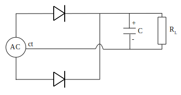
DC output generated by a rectifier circuit, not a wave of pure DC, but the waveform up and down or pulsing. These waves can not be used to distribute electronic circuits.

Process of flattening the pulsing waves of rectifier circuit, it can be done by connecting in parallel a large value of filter capacitor to output DC, as in the circuit below

filter capacitor to output DC
The capacitor used is usually electrolytic capacitors (elco) and has a capacitance value of 1000 μF or more. DC pulses from rectifier circuit are generated continuously and will fill capacitor immediately, until the voltage reaches maximum value.

When the load draw current of the circuit, the voltage on capacitor bit by bit away from maximum value, but the voltage will be immediately returned to maximum value by the next pulse. The result is a DC waveform with a little wave ripple.

DC waveform with a little wave ripple
DC waveform with a little wave ripple like picture above, can use to supply or distribute electronic circuit. It's almost a wave of pure DC.

Read more »»

Current output generated by half-wave rectifier circuit, is only worth half input cycle. This means that half of the input power is wasted.

Rectifier would be better, when using two diodes in series. Consider the circuit below

rectifier-two-diode
On positive cycle and negative cycle of the AC waveform, given a forward bias diode. Current flows through two diodes to the load and returned to the transformer through the ct (center tap). So that the circuit can be considered to consist of two half-wave rectifier circuit that works in turn.

Waveform at the output of which is at the end of RL load is shown in the picture below

full-wave-rectifier-circuit
Rectifier circuit is still generating output during the second half-wave cycles (cycles of positive and negative). So this series 100% efficient, because there is no input power is wasted. The circuit is called a full wave rectifier circuit.

Read more »»

One of most important use of diodes based on the ability of diode to conduct current in only one direction. When the diode is mounted on an alternating current or AC current, then the sine wave is converted into unidirectional wave or DC current.

Watch what happens to the circuit below

rectifier-circuit
Electrical current is supplied to the circuit is an alternating current generated by a transformer. During the positive half cycle of AC, diodes are forward biased so current can flow. Current that flows through the diode to the load (RL) and back toward the transformer. Then the negative AC half cycle, diode does not conduct electric current, because given the reverse bias.

Waveforms of current through the load (RL) plot in the figure below.

half-wave-rectifier-circuit
A circuit that is capable of converting AC voltage into DC is called as a rectifier circuit (rectifier). While the rectifier circuit as above, producing output current from the positive half cycle of input, we call it a half-wave rectifier circuit.

Read more »»

To prevent damage to the LEDs due to the high voltage source, we must put in series a current limiter resistor. Resistance value appropriate to the LED current limiting resistor, can be calculated as follows.

The voltage source provided is VS (Volt). We want the LED current is I (Amperes). Assume that the LED forward voltage drop or VD to be produced is 2 V. Note the picture below

LED current limiting resistor
The voltage drop across the resistor R must be value VS - VD or equal to VS - 2. According to Ohm's Law, the value of this voltage drop should be equal to I x R, thus VS - 2 = I x R. Rearrange the equation to get the value of R will generate

VS - 2 = I x R
R = (VS - 2) / I

example question
An LED will be lit by the source voltage of 9 V and the estimated current draw of 15 mA, what is the value series resistors must be connected to the LED?

completion:
R = (VS - 2) / I
R = (9-2) V / 15 mA
R = 7 V / 0.015 A
R = 466.67 Ω
Obtained value of 466.67 Ω resistor or use a value of 470 Ω according to the reference value in the market.

Read more »»

Voltage divider circuit is also known as potential divider circuit. Input to a voltage divider circuit is Vin.

Vin voltage will drive current (I) through both resistors. Because of both resistors connected in series, then the same current will flows pass through each resistor.

Voltage-divider-circuit
Effective resistance of two series resistors are R1 + R2. Drop voltage across this combination of both resistor is a Vin, according to Ohm's Law, the current flowing is
I = Vin / (R1 + R2)
Voltage at R2 becomes
Vout = I x R2
Substituting the current (I) with the first equation
Vout = Vin x R2 / (R1 + R2)

This equation is an equation to calculate the output voltage generated by a voltage divider circuit. By selecting two resistor with resistance values suitable, we can get the value of any output voltage within the range 0 to Vin (Volt).

Read more »»

Previous