headerphoto
Showing posts with label electricity. Show all posts

We have four articles that used to calculate current, cos phi, HP and power of single phase motor. Now, we want to collect them, embrace the result of them, then rewrite them in this article, to be Data Sample of Single Phase Motor. I hope it will be usefull :hahaha:

Data Sample of Single Phase Motor

Voltage - Frequency - Power - Cos Phi - Current
110V - 60Hz - 272.25W - 0.75 - 3.3A
200V - 60Hz - 1500W - 0.79 - 9.5A
200V - 60Hz - 1865W - 0.8 - 11.656A
200V - 50Hz - 330W - 0.82 - 2A
220V - 50Hz - 200W - 0.733 - 1.24A
220V - 50Hz - 1200W - 0.83 - 6.572A
220V - 50Hz - 66W - 0.6 - 0.5A
220V - 50Hz - 2200W - 0.78 - 12.821A
400V - 70Hz - 2984W - 0.68 - 10.97A
400V - 70Hz - 2550W - 0.75 - 8.5A
400V - 70Hz - 2600W - 0.65 - 10A
400V - 60Hz - 4476W - 0.85 - 13.165A

The four articles that used to be data sample above are:
:1: How to calculate current motor value in single phase motor?
:2: How to calculate cos phi motor value in single phase motor?
:3: How to calculate power motor value in kW to HP?
:4: How to calculate power motor value in single phase motor?

Read more »»

:1: There is an electric motor that used to drive conveyor machine. The electric motor has specifications: voltage is 200 Volt single phase, frequency is 50 Hz, cos phi is 0.82 and real power on the name plate is 330 Watt. How many current of electricity will flow into the motor?

:catat: Answer:
V = 200 Volt
f = 50 Hz
Cos phi = 0.82
P = 330 W
I = ...?

===================================
The formula of real power electricity in single phase motor
P = V I Cos phi . . . . . (Watt)

:pin: then

The formula of current electricity in single phase motor
I = P / (V Cos phi) . . . . . (Ampere)

====================================

I = 330 / (200 * 0.82)
I = 2 A.

:2: In the chocolate factory has an electric motor that has specifications: voltage is 220 Volt single phase, frequency is 50 Hz, cos phi is 0.78 and real power on the name plate is 2.2 kW. How many current of electricity will flow into the motor?

:catat: Answer:
V = 220 Volt
f = 50 Hz
Cos φ = 0.78
P = 2.2 kW → convert kW into W → 2.2 * 103 W = 2200 W
I = ...?

I = P / (V Cos φ)
I = 2200 / (220 * 0.78)
I = 12.82 A.

:3: The electric motor has specifications: voltage is 400 Volt single phase, frequency is 60 Hz, Cos φ is 0.85 Ampere and real power on the name plate is 6 HP. How many current of electricity will flow into the motor?

:catat: Answer:
V = 400 Volt
f = 60 Hz
Cos φ = 0.85
P = 6 HP → convert HP into W → 6 * 746 W = 4476 W
I = ...?

I = P / (V Cos φ)
I = 4476 / (400 * 0.85)
I = 13.165 A.

Read more »»

:1: We have an electric motor that used to drive washing machine. The electric motor has specifications: voltage is 220 Volt single phase, frequency is 50 Hz, current of electricity is 1.24 Ampere and real power on the name plate is 200 Watt. How many cos phi of electricity of the motor?

:catat: Answer:
V = 220 Volt
f = 50 Hz
I = 1.24 A
P = 200 W
Cos phi = ...?

===================================
The formula of real power electricity in single phase motor
P = V I Cos phi . . . . . (Watt)

then

The formula of cos phi in single phase motor
Cos phi = P / (V I)
or
Cos φ = P / (V I)

====================================

Cos phi = 200 / (220 * 1.24)
Cos phi = 0.733.

:2: In the paper bag factory has an electric motor that has specifications: voltage is 200 Volt single phase, frequency is 60 Hz, current of electricity is 9.5 Ampere and real power on the name plate is 1.5 kW. How many cos φ of electricity of the motor?

:catat: Answer:
V = 200 Volt
f = 60 Hz
I = 9.5 A
P = 1.5 kW → convert kW into W → 1.5 * 103 W = 1500 W
Cos φ = ...?

Cos φ = P / (V I)
Cos φ = 1500 / (200 * 9.5)
Cos φ = 0.79.

:3: The electric motor has specifications: voltage is 400 Volt single phase, frequency is 70 Hz, current of electricity is 10.97 Ampere and real power on the name plate is 4 HP. How many cos φ of electricity of the motor?

:catat: Answer:
V = 400 Volt
f = 70 Hz
I = 10.97 A
P = 4 HP → convert HP into W → 4 * 746 W = 2984 W
Cos φ = ...?

Cos φ = P / (V I)
Cos φ = 2984 / (400 * 10.97)
Cos φ = 0.68.

Read more »»

:1: There is an electric motor that used to drive water pump machine. The electric motor has specification: voltage 220 Volt single phase, frequency 50 Hz, current 9 Ampere and power 1.2 kW. How many horse power or HP power of electricity that used the motor?

:catat: Answer:
V = 220 Volt
f = 50 Hz
I = 9 A
P = 1.2 kW
P = ...? HP

====================================
The conversion formula of kW to HP
1 kW = 1/ 0.746 HP

=====================================

P = 1.2 / 0.746 HP
P = 1.61 HP.

:2: In the workshop has an electric motor that has specification: voltage 200 Volt single phase, frequency 60 Hz, and power 2.5 HP. How many kilo Watt power of electricity that used the motor?

:catat: Answer:
V = 200 Volt
f = 60 Hz
P = 2.5 HP
P = ...? kW

====================================
The conversion formula of HP to kW
1 HP = 0.746 kW

=====================================

P = 2.5 * 0.746 kW
P = 1.865 kW.

:3: The electric motor has specification: voltage 400 Volt single phase, frequency 70 Hz, current 8.5 Ampere and cos phi 0.75. How many horse power or HP power of electricity that used the motor?

:catat: Answer:
V = 400 Volt
f = 70 Hz
I = 8.5 A
Cos phi = 0.75
P = ...? HP

P = V I Cos phi
P = 400 * 8.5 * 0.75
P = 2550 Watt
P = 2.55 kW
P = 3.418 HP.

Read more »»

:1: We have an electric motor that used to drive fan machine. The electric motor has specification: voltage 220 Volt single phase, frequency 50 Hz, current 0.5 Ampere and cos phi 0.6. How many power of electric that used the motor?


:catat: Answer:
V = 220 Volt
f = 50 Hz
I = 0.5 A
Cos phi = 0.6
P = ... ?

P = V I Cos phi
P = 220 * 0.5 * 0.6
P = 66 Watt.

:2: The electric motor has specification: voltage 110 Volt single phase, frequency 60 Hz, current 3.3 Ampere and cos phi 0.75. How many power of electric that used the motor?

:catat: Answer:
V = 110 Volt
f = 60 Hz
I = 3.3 A
Cos phi = 0.75
P = ... ?

P = V I Cos phi
P = 110 * 3.3 * 0.75
P = 272.25 Watt.

:3: The electric motor has specification: voltage 400 Volt single phase, frequency 70 Hz, current 10 Ampere and cos phi 0.65. How many kilo Watt power of electric that used the motor?

:catat: Answer:
V = 400 Volt
f = 70 Hz
I = 10 A
Cos phi = 0.65
P = ... ?

P = V I Cos phi
P = 400 * 10 * 0.65
P = 2600 Watt
P = 2.6 kW.

Read more »»

We will use three unit of BSH 222 switch for control a motor glue pump. The glue must distribute to three different location, such us Line1, Line2 and Line3. Each switch store in each Line location.

Wiring diagram 3 phase motor 3.3 kW with three unit of BSH 222 switch

wiring_motor_3_phase_3.3kw_with_3_switch_bsh_222

Electric parts needed for the wiring 3 Phase motor 3.3 kW with three unit of BSH 222 switch above:

  • B1 = MCB 15A 3 phase
  • M1 = Motor 3.3kW 380V 3Phase
  • #1 = Magnetic contactor 220VAC
  • TOR = Thermal overload relay 6.3A
  • S1, S2, S3 = Push button switch type BSH 222
  • L3 = Pilot lamp 220VAC

Wiring connection of BSH 222 switch

switch_bsh_222_connection

BHS 222 switch has an two contacts switch, NO (Normally Open for ON button) Contact and NC (Normally Close for OFF button) contact. In wiring 3 Phase motor 3.3 kW with three unit of BSH 222 switch, we use to series connection the NC contact and to parallel connection the NO contact.

Read more »»

BSH 222 is a Type of Push Button Switch

Kasuga BSH 222 is a type of push button switch, which has an ON button and an OFF button in one switch. ON button BSH 222 marked with black color, position above OFF button. OFF button BSH 222 marked with red color, position below ON button.

BSH 222

PTM and PTB

ON button in a BSH 222 switch is type of PTM (push to make) non latching. OFF button in a BSH 222 switch is type of PTB (push to brake) non latching. Picture below is a symbol of BHS 222 switch.


Contact Capacity

Electric voltage and current capacity of the contact point BSH 222:
250 V max 5 A
500 V max 1 A.

Purpose

BSH 222 switch usually used for control (start and stop) small electric motor. For some case, one motor is controlled by many BSH 222 switch. One unit BSH 222 and other unit of them, are placed in different location, use for control a motor, such us motor glue pump who will distribute the glue for each location.

Read more »»

In the industrial world that use machine tools, there is a conveyor. The conveyor is used to move or distribute the products produced by the industry itself. Example of a conveyor as shown in the picture below

sample conveyor

Wiring diagram or simple start-stop control circuit one motor conveyor is shown below

wiring-diagram-one-motor-conveyorClick to enlarge

Electric parts needed for the wiring above:
1. Breaker NFB 3P 10 A 1 pc
2. Transformer (step down) 380 V / 220 V 3 A 1 pc
3. Magnetic Contactor 3P coil 220 V 1 pc
4. Thermal Over load Relay 1 pc
5. Fuse glass 2 A dan 3 A @ 1 pc
6. Pilot lamp 220 V 1 pc
7. Start button 1pc
8. Stop button 1 pc
9. Motor

Read more »»

In most cases compressor driven by the large power motor, above 10 KW. That used to generate the huge air pressure anyway.

Example of compressor with power 30 KW (40 HP) as shown in the picture below.

compressor with power 30 KW
To reduce inrush current (electric current of early motion) that can reach 200% to 300% of normal current when the motor will rotate, the system needs to be made such a wiring diagram star-triangle (star-delta) switching, as shown by the picture below.

(star-delta) switchingClick to enlarge
Electric parts needed for the wiring above:
1. Breaker 100 A 1 pc
2. Transformer step down 380 V / 220 V 3 A 1 pc
3. Magnetic contactor 3P 55 KW coil 220 V 3 pcs
4. Power on delay (Timer) 220 V 1 pc
5. Thermal over load relay 65 A 1 pc
6. Fuse glass 2 A dan 3 A @ 1 pc
7. Start button 1 pc
8. Stop button 1 pc
9. Motor 37 KW 380 V 3 φ 1 unit

Read more »»

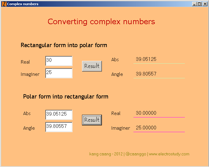
As someone who studied electricity, you will be confused with the imaginary calculations such as: (30 + j25) × (40 ∟ 65°). Two models number in parentheses is a complex numbers, where 30 + j25 is call rectangular form and 40 ∟ 65° is call polar form.

Rectangular form is a number that can be put in the form x + jy, where x and y are real numbers and j is called the imaginary unit. In this expression, x is called the real part and y the imaginary part of the complex number.

Polar form is a number that can be put in the form r ∟ φ°, where r is absolute value and φ is angle value. Together, r and φ give another way of representing complex numbers.

To solve the above calculations problem, you should have a scientific calculator, and you should know how to operate it. Can you do it? And to make it easier I will give complex numbers conversion software, free for you.

Download at Google code here ★ Converting complex numbers ★. Download and save rar file (size 10.4 kB), extract and run, as shown below


Read more »»

Magnetic relay or just called relay is a type of switch that is controlled by an electric current. The main part of relay consists of a coil and contacts. Relay coil wrapped around the core. There is an iron armature will be attracted to the core when a current flows through the coil. Armature is mounted on a spring-loaded lever. When the armature attracted to the core, relay contact will change its position from normally closed contacts to the normally open contacts.

A relay can be activated in about 10 ms. Most relay placed in packaging that fully closed, as shown below.

relay

Most among the relay has contacts type of SPDT switch, but there are also several types of DPDT switch, TPDT switch (Triple Pole Double Throw) and QPDT switch (Quadruple Pole Double Throw, as shown above right).

The important thing to note on a relay that will be used is the coil voltage and the maximum, current and voltage contacts.

Larger relays can be connected to the currents up to 10 A at a voltage of 250 VAC. The DC maximum voltage for switching is always lower than AC maximum voltage, sometimes even just half of the AC maximum voltage.

Symbol relay with QPDT contact switch

Symbol relay

Read more »»

micro switchMicro term on the micro switch, doesn't mean that the size of micro switch is small. This name indicates that the keys used to operate micro switch, only shifted by a very small distance.

Micro switch is type of very sensitive switch, just a little pressure on a lever may cause the switch move from one position to another. Most micro switches have contacts SPDT type, so that the switch can be used to connect or disconnect, or both simultaneously.

SPDT contacts in the micro switch is generally composed of three terminal tag, such a Common line, NO (Normally Open) contact and NC (Normally Closed) contact. Contacts are equipped with spring-loaded, on normal condition, Common line will be connected to NC contact.

There are various types of micro switch, which can be used according to the applications where the switch should be operated mechanically. Image below shows the various types of micro switches.

macam-macam-microswitch.jpg

For example, a micro switch can be mounted in such a way in a refrigerator. Common line and NC contact connected to a lamp. When the door closed, contacts will open and the light will turn off. When the doors opened, the contacts will close and light will turn on.

Read more »»

Key switch
Key switch is a type of switch that can only be turned on and turned off by using a key. Only a key partner and the right locking device which can be used to operate the switch. Key switch can be used in applications that require high levels of security, such as electrical control circuit in the industry.

Examples of key switch as shown in the picture below

Key switch
DPDT switch
Toggle switch, rocker switch, and slide switch, can also be made ​​in a Double Pole Double Throw version, which is abbreviated with DPDT switch. Form of this switch combine two separate switches in one unit, but they operated together.

DPDT switch can be used to connect two circuits at the same time. These switches can also be connected to the neutral wire line and the line wire voltage of the source at once. When a switch is in off state, the electrical equipment connected to the switch is totally isolated from the source voltage.

Symbol of DPDT switch as shown in the picture below

Symbol of DPDT switch

Read more »»

Rocker switch
Rocker switch works the same way as a toggle switch, where there is a lever that can be pressed up and down. Lever of the rocker switches are usually called to rocker lever, shaped like an electric bell button.

Generally there are two numbers on the rocker lever, numbers 1 and 0. When the lever is pressed on number 1, indicating that the switch in the On position, and when the lever is pressed on number 0, indicating a switch in the Off position.

Examples of rocker switch as shown below

Rocker switch
Slide switch
Slide switches are used for similar purposes to the use of toggle switches, but the slide switch is operated by using a sliding knob.

Examples of slide switches as shown in the picture below

Slide switch

Read more »»

Rotary switchRotary switch is a switch type which is operated by way of played. These switches are used to connect one line to one other line, among several lines that already exist. Often, several pieces of rotary switch is used in the same unit.
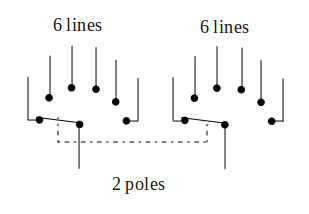
Examples of common use rotary switch is serves to select a range of measurements on an AVO meter or a multimeter, or to choose a power supply voltage. This type of switch has one or more contacts are surrounded by a ring with 12 stationary contacts. Such switches are made with the composition different contacts. These arrangements can be either 1 pole of 12 lines, 2 poles 6 lines, 3 poles 4 lines or 4 poles 3 lines.

The symbol of rotary switch with 2 poles 6 lines shown bellow

rotary-switc-2-poles-6-lines

Read more »»

Press switchPress switch is a type of switch that is operated by pressing a button. There are two types of press switch, ie push to make (PTM) switch and push to break (PTB) switch.

Most of the press switch is a kind of the PTM switch. By pressing a button PTM switch, the contacts will be depressed until the switch is closed and touch each other. While by pressing a button switch type of PTB switch, the contacts are normally closed contact, but will be forced open when the button is pressed.

Each type of PTM switch and PTB switch, can work to connect or disconnect during a moment or locking (latching). A switch work during a moment, will close (connect) or open (disconnect) as long as the button is pressed. When the button is released the switch will return to its original position.

Connection on the switch that locks, the button will remain in a depressed position after the first time pressed. Switch contacts will remain closed or open, depending on the type of switch is concerned. You must press the button again to unlock and return the buttons to its normal position.

Press switches are widely used in various industrial applications, the motor control circuit, and can also be used to connect power to the lights, radio devices, and other electrical equipment.

Symbol press switch such us PTM switch and PTB switch as shown below

Symbol press switch such us PTM switch and PTB switch

Read more »»

Toggle switchToggle switch is the simplest form of switch, operated by a toggle lever that can be pressed up and down. According to the convention, position of the lever downwards to indicate OFF conditions or switch contacts is disconnected, and position of the lever upwards to indicate ON conditions or switch contacts are connected.

Toggle switch have two terminal tag, which indicates that switch have a contact type single pole single throw or single pole single direction, which is usually referred to as SPST switch.

Toggle switch that are smaller have three terminals tag, which indicates that switch have a contact type single pole double throw or single pole two direction, normally abbreviated with the SPDT switch. Terminal tag at the center is the line common current flow and can establish contact with either of these two other tag. Such contacts are called changeover contacts switch.

Symbol for SPST switch and SPDT switch as shown below

Symbol for SPST and SPDT switches

Read more »»

The switch is a device used to control the flow of electrical current into the circuit. In the previous discussion about electric current, the electrical current will only flow in a closed circuit. So as to create a current to flow or not, we can use the switch.

Current flows when the switch contacts touch each other. In this state, the switch is said to be closed or made ​​contact.

Current can not flow into the circuit when the contacts are not touching. In this state the switch is said to be opened or lost contact.

Other terms of the condition of the switch is On and Off. On condition occurs when the contacts is made​​, and the Off condition occurs when the contact is lost.

symbols-of-switch
There are various types of switches are used for many different purposes. Figure above shows the general symbols of switch, Off the conditions shown in Figure A, and On conditions are shown in Figure B.

Read more »»

lightReflection
Whenever light falls onto surface, some of it is absorbed and the remainder is either reflected or transmitted. If the surface is opaque and smoothly polished, the specularly reflected light leaves the surface at the same angle as is arrived (as a billiard ball striking a cushion), and by suitably shaping the surface it is possible to redirect the light in any desired direction (e.g. a motor car headlight, with lamp placed at the focal point of a polished parabolic mirror directing most of the light forward).

Diffuse reflection occurs from matt surfaces. The light is reflected most strongly at right angles to the surface (whatever the direction from which the light arrives) and progressively more weakly at other angles. Matt surface show no highlights. Most painted and many other surfaces are partly specular and partly diffuse reflectors of a light and are classified according to which type or reflection predominates.

Diffusion
Light passes straight through a transparent material, but it scattered or diffused to a greater or lesser extent in a translucent material. Flashed opal glass or its plastics equivalent scatters it completely so that it emerges in all directions, and complete concealment of lamps behind a panel of this material is easy achieved. Frosted glass diffuses the light less perfectly, so that it emerges mainly in the same general direction as when it entered the glass; in effect, it is usually possible to see vaguely the positions of lighted lamps behind frosted panels. Hammered and rolled glasses and clear plastics with a similar finish generally have less diffusing and concealing power than frosted glass but have a sparkle that may be preferred in many cases.

Refraction
If light passes through a transparent material which does not have parallel side, it will be bent away from its original direction by a process known as refraction. Ribbed glass or plastic fittings in which each rib is a carefully designed prism can therefore be made to control light very accurately in a required direction, and this principle is very widely used in electric street lighting fittings.

Read more »»

Virtually all buildings have electric lighting which serves two purpose. It help us to recognise objects quickly and in sufficient detail to learn all we need to know about them, and it contributes to making buildings safe and pleasant place in which to work or take part in other activities.

There must always be enough light to make object visible but other factors are no less important. The directions from which light come, the brightness and color contrasts created between details of interest and their background, the presence or absence of bright reflections in the part of the object being looked at, and changes in color resulting from the type of lamp used can all effect ease of recognition.

Some of the more common terms used in lighting design and the associated units are given below
Luminous flux. The light emitted by a source, or received by a surface. It is expressed in lumens. Symbol: Ø
Lumen. This is the SI (Standard International) unit of luminous flux. An ordinary 100W lamp for example emits about 1200 lumen. One lumen is the luminous flux emitted within solid angle (one steradian) by a point source having intensity of one candela. Symbol: lm
Luminous intensity. The quantity which describes the power of a source or illuminated surface to emit light in a given direction. It is the luminous flux emitted in very narrow cone containing the given direction divided by the solid angle of the cone. The result is expressed in candelas. Symbol: I
Candela. The SI unit of intensity. It is lumen per steradian. Symbol: cd
Illuminance. The luminous flux density at a surface, i.e. the luminous flux incident per unit area. The quantity was formerly know as the illumination value or illumination level. It is expressed in lux (lumens/m2 or lm/m2). Symbol: E
Lux. SI unit of illuminance. It is equal to one lumen per square meter.
Room index. An index related to the dimensions of a room, and used when calculating the utilization factor and the characteristics of a lighting installation. It is given bellow
lw / hm (l + w)
where l is the length and w the width of the room and hm the height of luminaires above the working plane.

Read more »»

Previous